Precision Tools
QUICK SUMMARY
- Use Grids to create consistent layouts and perspectives.
- Use Snap to make your strokes follow grid lines or snap to other key points.
- Set scale for your drawing to work with real-world measurements.
- Activate a Shape Guide or use the Shape Recognition to draw perfect squares, circles, and more.
Concepts has several Precision Tools to help you achieve accurate lines, perfect shapes, and precise measurements in your drawings. You can also set a scale for your designs.
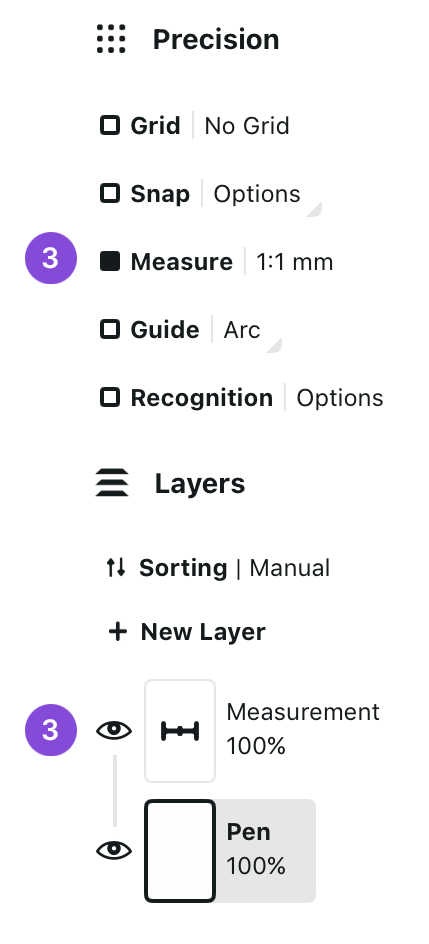
Interface

- Toggle Precision. Tap the Precision icon in the status bar to show or hide the Precision panel.
- Precision. Tap the Precision button to minimize the Precision panel.
- Grid. Toggle Grid by tapping the checkbox. Tap the other side to access your Grid options.
- Snap. Toggle Snap by tapping the checkbox. Tap the other side to open the Snap menu.
- Measure. Toggle Measure by tapping the checkbox. Tap the other side to open your Measurement settings.
- Guide. Toggle the Shape Guide by tapping the checkbox. Tap the other side to open your Shape Guide menu.
- Recognition. Toggle the Shape Recognition by tapping the checkbox. Tap the other side to open your Shape Recognition settings.
Grids

Grid is a framework that helps you structure your content. You can use the grid as a visual reference, or you can have your strokes either Snap to or Align with the grid.

- Tap Grid under Precision to toggle the grid on or off.
- Tap the label with the grid name to bring up the Workspace to choose the grid type.

- Once you have enabled the grid, a Grid layer will be added to your Layers. You can drag the Grid layer anywhere in your Layers list. Note that you cannot draw or drag any selections to the grid layer.
Grid Layer
Once you have activated the grid in the Precision menu, the Grid Layer is added to the bottom of your layer list.

- You can Tap+Hold+Drag the Grid Layer to move it anywhere on the layer list.
- Double-tap the Grid Layer to enter Focus Mode.
In the Grid Layer menu, you will find:
- Delete layer button. This will delete your grid and toggle the Grid off.
- Tap the Settings button to get to the Grid Settings.
- Drag the slider to adjust the opacity of the Grid Layer.
Grid Types

Concepts has five basic grids and three perspective grids: Dot Grid, Graph Paper, Lined Paper, Isometric Grid, Triangle Grid, and 1, 2 and 3 Point Perspectives. Select the grid from the list in the Workspace menu.

- Scroll the list of grids in Settings -> Workspace.
- Tap to choose a grid type.
- To edit the grid or choose from the grid presets, tap the active grid or tap the Edit Grid button.
Basic Grids
With the basic grids, you can edit several settings. Note that the grid units are determined by the drawing units you've selected in the Workspace menu.

- Preset. Choose from several grid presets.
- Spacing. Spacing defines the distance between the main lines or dots.
- Divisions. Divisions determine how many subdivisions there are between the major lines. Set value to 1 to only show the main lines. Available for Graph Paper and Lined Paper grids.
- Line Weight. Set the thickness of the grid lines.
- Color. Use the automatic color that adapts to your canvas or choose a custom color.
- Opacity. Set the opacity of the grid. This option is available when using a custom color.
- Orientation. Set the orientation of the grid to landscape or portrait. Available for Lined Paper, Isometric Grid, and Triangle Grid.
- Confine to Artboard. This confines the grid lines to only show within the artboard. This option only has an effect if there is an artboard on canvas.
Perspective Grids
With the perspective grids, you can edit several settings. Editing the vanishing points happens directly on the Canvas. Note that the grid units are determined by the drawing units you've selected in the Workspace menu.

- Preset. Choose from several grid presets.
- Vanishing Points. Tapping this button takes you to the canvas, where you can move the vanishing points and adjust the grid to your liking. You can also edit the grid on canvas at any time by Tap+Holding on the vanishing points or by activating the Grid layer.
- Density. Choose the number of vanishing lines that appear in the grid.
- Line Weight. Set the thickness of the grid lines.
- Color. Use the automatic color that adapts to your canvas or choose a custom color.
- Opacity. Set the opacity of the grid. This option is available when using a custom color.
- Orientation. Set the grid orientation of the grid to landscape or portrait. By default, the grid is created in the same orientation the device was in when the drawing was created.
- Confine to Artboard. This confines the grid lines to only show within the artboard. This option only has an effect if there is an artboard on canvas.
Editing Grids on Canvas

You can also edit the grids directly on the canvas.

- To enter the grid edit mode, activate the Grid layer in the Layers menu.
- With perspective grids, you can access the grid editing mode also by Tap+Holding on a vanishing point.
While the Grid layer is active, zooming and panning the canvas work normally, but it is also possible to edit the grid. All grids have a rotation handle that you can use to set the grid to a specific angle.

- Drag the handle to rotate the grid.
- A snap target line is shown every 45 degrees. Release the handle while the snap target line is showing to snap to that angle, or keep the handle still and wait for the snap target line to disappear to set a specific angle close to the snap.
- When rotating the grid, the angle is shown in the status bar. Tap+Hold the value to edit it directly.

- To move the grid, drag the grid from the crosshairs at the center of the horizon line, or drag the line itself.
- With the perspective grids, you can move all of the vanishing points by dragging them.

- Tap the vanishing points to activate them. When the points are active, you can pan them with one finger or move them around with two fingers just like when adjusting a Selection. To scale the grid, select all vanishing points and use two fingers to scale.
- Tap Done in the Editing Grid toast notification to exit the grid editing mode. You can also tap away from the editing controls on canvas or activate another layer.
Snap
You can use Snap in two ways in Concepts: snapping while drawing, and snapping while editing.

- Tap Snap under Precision to toggle the snapping on or off.
- Tap the Options to bring up the Snapping Options.
Snap Options
When you open the menu for Snap Options, you will see a variety of options for snapping while drawing and editing.
Snap While Drawing


- Snap to Grid. With this option enabled, all strokes are drawn to follow the closest grid line available. The Wire and Fixed Width brushes can be used to draw strokes with fewer points. Try these tools if you want to export SVG or DXF.
- Align to Grid. This option aligns strokes directionally with the grid lines but does not limit them to the grid lines.
- Allow Traceback. With the Allow Traceback option toggled, you can retrace your strokes and redo your lines.
- Allow Turns. Enable this option to allow making turns when drawing while drawing with Snap and Align to Grid.
- Auto-complete. Connects the start and end points of your strokes. You will see small circles appear showing you possible points to connect to. Tap the one you want to connect to. Autocomplete can be used together with Snap to Grid and Align to Grid. With Align to Grid, the strokes can snap to any strokes intersecting with the trajectory of the stroke.
- Active Layer Only. This option only applies to the auto-complete. Activate this option to only auto-complete to lines on the currently active layer.
Drawing with Snap + Grids
When drawing with Snap, each grid has its own guide settings that correspond with the grid's directional constraints.
- Dot Grid
- Snap: Draw horizontal and vertical lines only.
- Align: Draw horizontal, vertical, and 45-degree diagonal lines.
- Graph Paper
- Snap: Draw horizontal and vertical lines only.
- Align: Draw horizontal, vertical, and 45-degree diagonal lines.
- Lined Paper
- Snap: Draw horizontal and vertical lines only.
- Align: Draw horizontal, vertical, and 45-degree diagonal lines.
- Isometric Grid
- Snap + Align: Draw 60-degree diagonal lines only.
- Triangle Grid
- Snap + Align: Draw 60-degree diagonal lines only.
- 1 Point Perspective
- Align: Draw horizontal and vertical lines, and perspective lines directing toward the single vanishing point on the horizon line.
- 2 Point Perspective
- Align: Draw vertical lines, and perspective lines directing to each of the two vanishing points on the horizon line.
- 3 Point Perspective
- Align: Draw perspective lines only that direct toward any of the three vanishing points on the canvas.
Snap While Editing

When you Select a previously drawn stroke, you can adjust and move it with the help of Snap. You can snap the stroke to other key points or to the grid.

- Snap to Grid. Snap to Grid snaps the key points of your selection to the grid.
- Snap to Key Points. Snap to Key Points snaps the key points of your selection to the key points of other strokes.
- Active Layer Only. Active Layer Only allows you to snap to strokes on the current layer only.
Snap Points
Depending on how the stroke was created, it has different snap points it will use to snap with.
- With single-stroke selections, Snap points are the beginning and end points of any given line, and the four corners and the center point.
- If the stroke is drawn with Snap to Grid, the apexes work as Snap targets as well.
- With multi-stroke selections, Snap applies to the four corners and the center point of the selection.
- When used with Shape Guides, Snap applies to the handles and the center point.
Grid Drawing Tutorials
We have several illustrated tutorials available for learning to set up and draw with the grids, and improve your perspective drawing skills.
- How to Set Up a Perspective Grid in Concepts - Learn how to set up and customize your perspective grids in Concepts.
- How to Sketch with a Perspective Grid - These drawing exercises will help you learn how to use 1 point, 2 point and 3 point perspective grids to sketch designs and illustrations.
- Learn to Draw: Basics of Perspective - Part of our Learn to Draw Series, this video tutorial will help you to understand the fundamentals of perspective drawing.
- How to Create Lined Paper - Learn how to set up lined paper for note taking and handwriting practice on your infinite canvas.
Measure

In Concepts, all the strokes, selections, and imported items have measurement data attached to them. These measurements are not visible by default, but you can display them by enabling the Measure option in the Precision menu.
Setting up the measurements

- Tap Measure under Precision to toggle the Measurements on or off.
- Tap the unit and scale on the other side of the toggle to see and edit your Measurement Options.
Measurement Options

- Drawing Scale. Define your Drawing Scale. You can choose from one of the presets or set a custom scale.
- Display Units. Concepts offers different unit systems: Digital, Metric, and Imperial.
- Display Format & Precision. Set the display format and fidelity of precision for your measurements.
- If you want to change the side where the measurement labels are shown, toggle the Show stroke on the right side while drawing. This is useful if you are left-handed.
- If you want to show the percentage value of your selection's Width and Height, toggle the Show scale in the status bar for selections option.
Measurement Layer
Once you have activated the Measure in the Precision menu, the Measurement Layer is added to the top of your layer list. The Measurement Layer also allows adding static measurements to your drawing that are not associated with any strokes.

- You can Tap+Hold+Drag the Measurement Layer to move it anywhere on the layer list.
- Double-tap the Measurement Layer to enter Focus Mode.
In the Measurement Layer menu, you will find:
- Delete layer button. This will delete your Measurement Layer and toggle Measure off. Please note that this will also delete all the measurements you might have added to your drawing.
- Tap the Settings button to access the Measurement Settings.
- Drag the slider to adjust the opacity of the Measurement Layer.
How to set Drawing Scale and Units

Scale is the ratio between the size of something in drawing and its actual size. For example in 1:100 scale, a 1 cm line on the screen represents a 100 cm line.

- To set your Drawing Scale and Units, go to Settings -> Workspace -> Measurements -> Drawing Scale. Choose one of the scale presets or set a custom scale.
- Set your Units. Select the units you want to use from Digital, Imperial, and Metric.
- Choose the Format and Precision your units are displayed in.
After setting your units and scale, all tool and measurement values will appear according to the selected scale. For example, when changing from points to inches, a pen set to 2 points would be converted to 0.015 inches. Your tool presets will remain the size you have set, but the units will be converted.
How to Set Scale with an Imported Plan or Photo
If you want to set scale accurately in a project, you will need to know one accurate measure for reference.

- Import a reference image onto your canvas.
- Turn on Precision, and activate Measure.
- Activate the Line guide.

- Align the handles on your reference image to the segment for which you know the measure.
- Double-tap the crosshairs at the center of the Line guide to contain the boundaries of the line to your measurement when you draw.
- Tap the 1:1 ratio beside Measure, or the 1:n Set Scale in the bottom menu.

- You will notice the values under Drawing Scale have been filled in with the current length of the Line guide.
- Enter your measure of reference in the second field, and dismiss the menu. Your scale is now set to your measure of reference.
For a fully illustrated tutorial on setting scale, check out Scale and Measurement in Concepts.
Types of Measurement Labels
When Measure is active, a measurement label updates live with your stroke as you draw. You can also add static measurement labels to your plan for reference using the Shape Guides and Selections.
Dynamic Measurements
Dynamic measurements are live measurements associated with a drawn stroke or a filled in area. You will see these measurements update as you draw.

- When you tap a dynamic measurement label, it remains attached to your stroke and will "stick" on the layer you drew it on.
- Selecting a dynamic measurement will also select the stroke it is attached to. They will be treated as the same object when editing.

- Select a line or fill you've previously drawn to show its measurement label. Tap it to set it on the canvas.
Static Measurements
Static Measurements are measurement labels applied to the canvas when a line or fill is Selected, or when using a Shape Guide.


- A Shape Guide allows you to create a static measurement, or a label without an associated line. Just tap the shape guide's measurement label without tracing the corresponding line.

- You can also enter a custom value by Tap+Holding on your shape guide's measurement label, and the entire guide will adjust to your value.

- Static measurement labels are saved to the Measurement layer. This layer appears automatically when Measure is activated.
Drawing with measurements
When you start drawing with the Measure enabled, you can see a live measurement attached to your stroke showing the length or area of the stroke.

- When Measure is enabled, you will see the measurement attached to your stroke. Tap the measurement label to stick it to the canvas.

- If you want to resize your stroke to a certain length, select a stroke and then Tap+Hold its measurement label. You can also edit the stroke length by Tap+Holding the length indicator up in the status bar, or using the Measurement Popup.
- Note that measurement labels will only appear and export with your drawing:
- While Measure is active.
- When your Measurement layer is toggled to visible.
We have an illustrated tutorial on working with Scale and Measurement here. This tutorial walks you through how to work with measurement labels and how to set scale to drawings and imported plans of various types.
Area Measurement

The Fill tool is different from all the other brushes as it also shows the area. You can use this to estimate material consumption in your renovation plans or quickly check the size of a certain area in your plan.

- When drawing, the area measurement appears in the center of the fill. Once the fill is finished, tap the measurement to save it on canvas.

- You can resize your area to a certain measure. Select the fill and Tap+Hold the measurement label. You can also edit the stroke length by Tap+Holding the length indicator up in the status bar, or using the Measurement Popup.
Editing Measurements
To edit a Static Measurement label, select the label on the Measurement Layer.

- Copy to Clipboard. Copy the measurement label to clipboard.
- Duplicate. Duplicate the measurement label.
- Delete. Delete the measurement label.
- Flip Horizontally. Flips the measurement label horizontally. The label text will not be flipped.
- Flip Vertically. Flips the measurement label vertically. The label text will not be flipped.

- To reposition a label attached to a stroke, Tap+Hold+Drag the label along the stroke path.
Measurement Popup

On the Status Bar, you will see a field stating your current relevant zoom, rotation and selection status. In the Measurement Popup, you can quickly access zoom and rotation presets for your canvas or selection, lock and unlock canvas zoom and rotations, and use the fields to control a selection's dimensions.
- With a single stroke selected, you will see the length, width, height and rotation of the stroke.
- With multiple strokes or an image selected, you will see the width, height and rotation of the selection.
- With a fill stroke selected, you will see the width, height, length, area and rotation of the selection.

- Tap on the measurement field in the status bar to open the Measurement Popup.

- Tap the values in the popup to inline edit them. You can enter measurements in any unit, and they will be automatically converted to match the document units you have selected in the Workspace Settings.
- You can lock or unlock the relation of width and height when adjusting the values. Tap the chain to toggle.
- You can use the presets to rotate and scale the selection.
Shape Guides

The Shape Guides are templates you can use to draw your desired shapes. Depending on the guide, you can control the width, height, edge, and radius of the guide to trace along.

- Tap Shape Guide under Precision to toggle the currently active Shape Guide on or off.
- Tap the Shape Guide name on the other side of the toggle to see the different Shape Guides.

- Concepts has five Shape Guide options; line, arc, angle, ellipse, and rectangle.
Using Shape Guides
When you activate a Shape Guide, you will see some additional elements on your canvas.

- The Shape Guide. The gray template shows the path where the stroke will be drawn. The thickness depends on your tool width. Draw anywhere on screen to draw the shape.
- The handles. Tap+Hold+Drag a handle to pull it to change the shape.
- The crosshairs. Tap+Drag the crosshairs at the center of the Shape Guide to move the guide. If you double-tap the crosshairs, each guide will respond with a special function:
- The Line guide will limit your drawn stroke to between the handles.
- The Arc guide will become a perfect half-circle.
- The Angle guide will snap to 90 degrees.
- The Ellipse guide will become a perfect circle.
- The Rectangle guide will become a perfect square.

- To rotate a Shape Guide, use the two-finger gesture. You can also use the angle field in the status bar at the top of the canvas, the "Rotate" tool, or the keyboard shortcut "R".
Using Shape Guides with Measurements
When you have both Shape Guide and Measure active, you will see the relevant measurements of your guide. You can Tap+Hold the measure to edit your guide accurately.
You can use the Shape Guides to create measurement labels that are not attached to a stroke. Read more about measurement labels created with Shape Guides in the Static Measurements section.
To set scale using the Line Guide, read the How to Set Scale with an Imported Plan or Photo section.
Shape Recognition
Shape Recognition allows you to quickly turn rough drawings into perfect shapes. Start drawing a shape and then hold at the end of the final stroke to detect a shape.

- Tap Recognition under Precision to toggle the Shape Recognition on or off.
- Tap the options on the other side of the toggle to see the options for the Shape Recognition.

- In Settings -> Interaction -> Draw & Hold menu, you can adjust the Shape Recognition Settings. You can toggle the "Enable Shape Recognition" to turn it on or off.
- You can change the Activation Time by adjusting the slider.
Using Shape Recognition

- Start by drawing a shape with one to four strokes.
- Hold at the end of the final stroke to detect a shape.
- When the shape has been detected, you can scale and rotate it by moving your stylus without lifting it from the screen.
Supported shapes include straight and curved lines, arrows, triangles, squares, rectangles, circles and ellipses.
If you're just getting started using the Precision Tools in Concepts and want some practice using the tools, check out our beginner tutorial How to Design in Concepts.