The Ultimate P&ID Library: Draft Precise Process Diagrams & Isometric Schematics in Minutes
Piping and Instrumentation Diagram Objects for iOS, Windows, Android and ChromeOS.
Learn how to find the P&ID Object Packs and what is included in the large library of isometric and 2D views.
What's inside?
A Piping and Instrumentation Diagram (P&ID) is the primary schematic used to document the relationship between piping, instrumentation and system equipment. These diagrams serve as the essential foundation for drafting, safety analysis and professional training.
To help you build these complex systems, we have curated a professional collection of industry-standard symbols. The Isometric P&ID Symbols and P&ID Symbols Object Packs allow you to quickly draft precise schematics. Combined, you will have a complete library of 107 components.
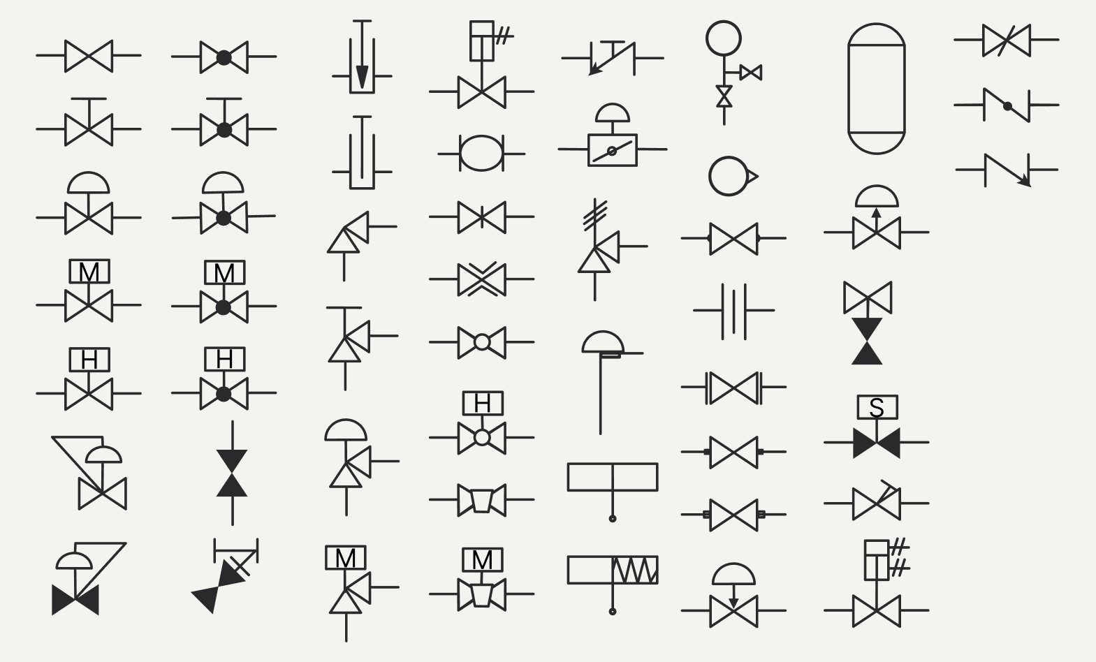
Overview of components in the P&ID Symbols Object Pack
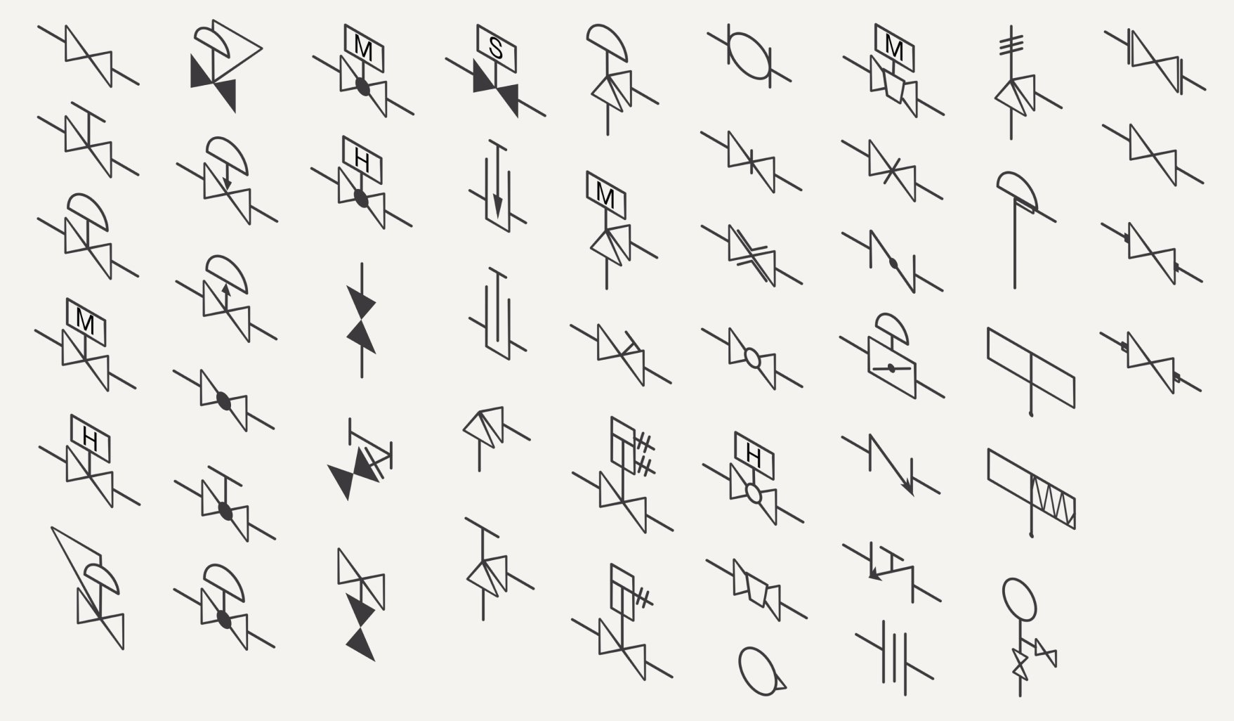
Overview of components in the Isometric P&ID Symbols Object Pack
The packs include:
- Extensive Valve Collection: Over 40 specialized valves including Gate, Globe, Ball, Butterfly, Plug, Check and Angle valves, plus fail-safe positions.
- Pressure & Safety Controls: Integrated Safety (PSV) and Relief (PRV) valves, plus high-precision pressure regulators.
- Instrumentation & Measurement: Essential gauges, rotameters and orifices to document system monitoring.
- Heavy Equipment: Standardized pumps, storage tanks, drums and end connectors (available in 2D).
- Dual-Perspective Mapping: Every valve and instrument is available in both Standard 2D and 3D Isometric views for total design flexibility.
The P&ID Object Packs are available with a monthly/yearly subscription, or as a one-time purchase in Concepts.
How to Find the P&ID Object Packs
Windows & Android: Find the Object Pack by opening up Concepts > tapping the Library icon at the top of your canvas > Object Market > P&ID Symbols & Isometric P&ID Symbols and start building!
iOS: Open up Concepts > tap the Library icon at the top of your canvas > More > in the Market tab, scroll down until you see P&ID Symbols & Isometric P&ID Symbols and start building!
How To Customize Your P&ID Objects
Change the Size

Every Object can be transformed, scaled and customized. Simply tap on the Object to add it to your canvas to get started.
Change up the Style

Apply different colors, opacity settings, brushes, and experiment with endless possibilities. Select your Object and tap on any brush you have set in your toolbar or tool wheel.
Nudge it

Try nudging your Objects to create new shapes that fit your layout and customize them even further.
Perfect For:
Empower your technical workflow with a versatile toolkit designed for those who design, manage and document complex fluid systems. You can create diagrams in 2D and 3D isometric views to match your project's needs.
- Process Engineers: Create clear, standardized P&IDs for plant operations and system documentation.
- Mechanical Designers: Move effortlessly between flat schematics and 3D-style isometric piping layouts.
- Project Managers: Quickly mock up system logic and feedback loops to communicate with technical teams.
- Industrial Educators: A perfect tool for teaching the fundamentals of fluid systems and instrumentation.
- Maintenance Teams: Generate easy-to-read "as-built" diagrams for site inspections and safety reviews.
💡 Pro-Tip for Your Workflow: While P&IDs are traditionally black and white, try color-coding for different line types (e.g., steam, water or chemical) while keeping the Object Pack symbols uniform. This maintains professional standards while making complex crossovers much easier to navigate at a glance.
We hope this Object Pack equips you with a great starting point to quickly move into your creative process.
Share your diagrams with us at support@concepts.app and tag us on Instagram @ConceptsApp. We can’t wait to see what you build.
Written By: Jessica Donnelly
Recommended
How to Measure in Concepts – In this Walkthrough Series playlist, you will learn how to use the Precision menu, Measure tool, Shape Guides and set scale to assist with creating engineering diagrams that meet professional standards.
How to Stay Organized with Layers – Learn how to use Layers to separate your piping, instrumentation and annotations, making it easy to edit dense system layouts without losing your flow.
Architectural Design Series: How to Create Floor Plans – This video tutorial by Architect Osama Elfar demonstrates the professional drafting techniques and organizational habits essential for any technical system design.